

ELECTOMAGNETISM
MAGNETIC FIELD RESULTING FROM ELECTRIC CURRENTS
Magnetic Field
Magnetic field is the region round a magnet where a magnetic force occurs. An electric current can produce a magnetic field, which can be visualized as a series of circular field lines around a wire segment.
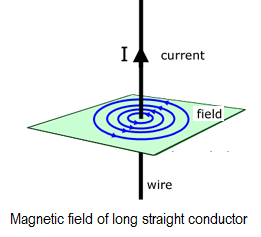
Electromagnetism is produced when an electrical current flows through a simple conductor such as a length of wire or cable, and as current passes along the whole of the conductor then a magnetic field is created along the whole of the conductor. The small magnetic field created around the conductor has a definite direction with both the “North” and “South” poles produced being determined by the direction of the electrical current flowing through the conductor.
Therefore, it is necessary to establish a relationship between current flowing through the conductor and the resultant magnetic field produced around it by this flow of current allowing us to define the relationship that exists between Electricity and Magnetism in the form of Electromagnetism.
Biot-Savart Law
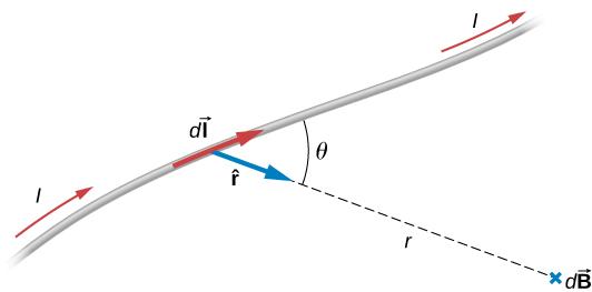
Biot-Savart law is an equation that describes the magnetic field created by a current carrying wire and allows calculating its strength at various points
The Biot-Savart can be explained in a simplest way from electric field;
The charges that are not moving create electric field and the charges that are moving create magnetic field.
The equation of stationary charges (electric field) is given by;
In a moving charges (magnetic field) the charge  represented by a current element
 and electric field E as Magnetic field B and now the equation is written as;
The formula  is called Biot-Savart Rule
is called Biot-Savart Rule
Where by the constant of proportionality  is known as the permeability of the medium and measured by henry per metre (Hm-1) while the strength of a magnetic field is measured B is measured by tesla (T)
is known as the permeability of the medium and measured by henry per metre (Hm-1) while the strength of a magnetic field is measured B is measured by tesla (T) when
when
APLICATION OF BIOT-SAVART
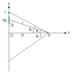
Magnetic field due to current of finite straight conductor
Since directions of magnetic fields due to all current elements are same, we can integrate the expression of magnitude as given by Biot-Savart law for the small current element (we have replaced dl by dy in accordance with notation in the figure below)
From,  ,
,
In order to evaluate this integral in terms of angle φ, we determine đy, r and θ in terms of perpendicular distance “R” (which is a constant for a given point) and angle “φ”.
Here,
Substituting in the integral, we have:

Magnetic field due to current of infinite straight conductor and point P lies at the centre of conductor
In this case, 
Magnetic field due to current of infinite straight conductor and point P lies at one end
In this case,  ,
, 
Examples:
A long straight wire carries a current of 50A. What is the magnetic field produced by current carrying long wire at a distance of 5 cm?
Solution:
Given:  ,
, 
At what distance from a long straight wire carrying a current of 12A will the magnetic field equal to ?
?
Solution:
Given:  ,
, 
A current of 1A is flowing in the sides of an equilateral triangle of side 2m. Find the magnetic field at the centroid of the triangle.
Solution:
Given:  ,
, 
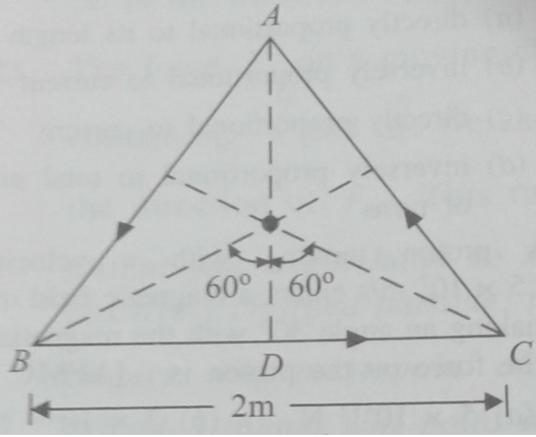
From the figure above;
The total magnetic field at the centre of the triangle is 
A wire placed along north-south direction carries a current of 5A from south to north. Find the magnetic field due to a 1 cm piece of wire at a point 200 cm north-east from the piece.
Solution:
Given:  ,
,  ,
,  ,
, 
A square loop of wire of side  carries a current
 . What is the magnetic field at the centre of the square?
Solution:
Consider the following figure:
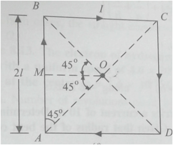
Given:  ,
, 
The total magnetic field at the centre of the triangle is 
Magnetic Field at the Centre of a Circular Coil
Consider the following diagram

According to Biot-Savart law, the magnetic field at the centre O of the coil for small length dl

The angle between dl and r, is 90. We will get total magnetic field at centre O by integrating the above equation. Limit of the integration will be  to
to  because length of the coil is circumference of the circle is
 .
.
From the Biot-Savart formula above;

If number of turns of the coil is n
Examples
- The plane of a circular coil is horizontal. It has 20 turns each of 8 cm radius. A current of 1A flow through it, which appears to be clockwise from a point vertically above. Find the magnitude and direction of the magnetic field at the centre of the coil.
Solution:
Given:  ,
,  ,
, 
2.The coil of radius 10 cm and having 20 turns carries a current of 12A in clockwise direction when seen from east. The coil is in north south plane. Find the magnetic field at the centre of the coil.

Solution:
Given:,  ,
, 
3.A circular coil of 100 turns has a radius of 10 cm and carries a current of 5A. Determine the magnetic field at the centre of the coil.
Solution:
Given: , ,
, , 
4.The wire shown below carries a current of 10A. Determine the magnitude of magnetic field induction at the centre O, if the radius of the coil is 3 cm.
Solution:
Given:  ,
,  i
i
5.A straight wire carrying a current of 12A is bent into a semicircular arc of radius 2.0 cm as shown below

Solution:
Given:,  ,
,

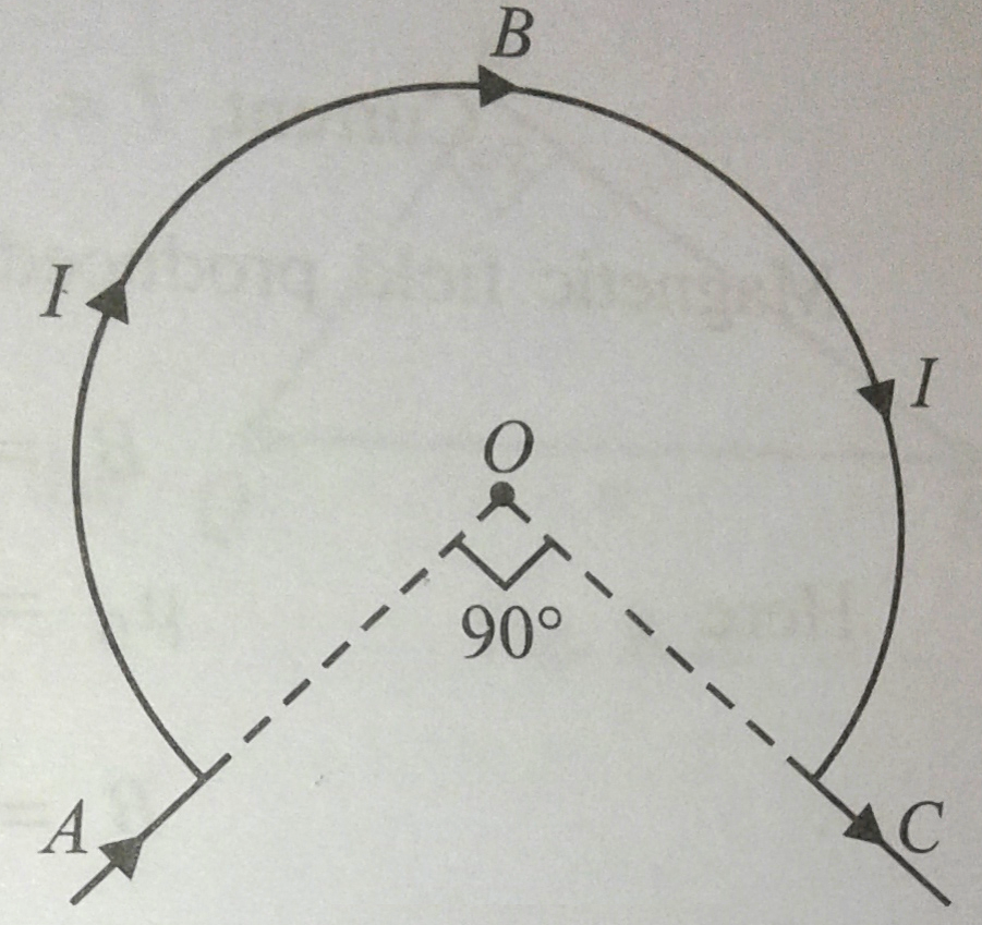
6.Find the magnetic field at the centre O of the following figure.

Given:  ,
, 
The Magnetic field at a point anywhere on the axis of a circular coil
Consider a circular coil of radius r, carrying a current I. Consider a point P, which is at a distance x from the centre of the coil. We can consider that the loop is made up of a large number of short elements, generating small magnetic fields. So the total field at P will be the sum of the contributions from all these elements. At the centre of the coil, the field will be uniform. As the location of the point increases from the centre of the coil, the field decreases.
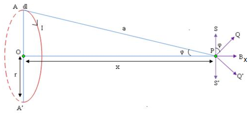
By Biot- Savart’s law, the field dB due to a small element dl of the circle, centered at A is given by,

The total magnetic field at a point which is at a distance x away from the axis of a circular coil of radius r is given by,
If there are n turns in the coil, then

Examples:
- A circular coil of 100 turns has a radius of 10 cm and carries a current of 5A. Determine the magnetic field at a point on the axis of the coil at a distance of 5 cm from the centre of the coil.
Solution:
Given:, , , 

- A flat circular coil of 120 turns has radius of 18 cm and carries a current of 3A. What is the magnetic field at a point on the axis of the coil at a distance from the centre equal to the radius of the coil?
Solution:
Given: ,
,  ,
,  ,
, 

- A 5 turns coils of radius 1 cm carries a current of 0.5 A. Calculate the magnetic field at point on the axis of the coil, situated at a distance of 1 m from the centre of the coil.
Solution:
Given: ,
,  ,
,  ,
, 

The Magnetic Field at the Centre of a Long Solenoid of N turns per Metre Carrying a Current I
A solenoid is a tightly wound helical coil of wire whose diameter is small compared to its length. The magnetic field generated in the centre, or core, of a current carrying solenoid is essentially uniform, and is directed along the axis of the solenoid.
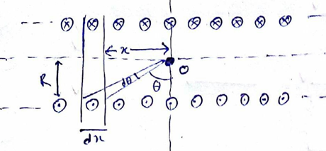
Let 'n' be the number turns per unit length of the solenoid. So in the length  there will be
  number of coils. The field experienced by an object O at the centre of this solenoid is given by:
 , Now we can substitute x as


Integrating the expression from  to
to  we get
The Magnetic Field at the End of a Long Solenoid of N turns per Metre Carrying a Current I
If the point P is lies on one end of the solenoid the expression  is integrated from
  to
to  , therefore


The Magnetic Field of Helmholtz Coil
A Helmholtz coil is a device for producing a region of nearly uniform magnetic field, named after the German physicist Hermann von Helmholtz. It consists of two solenoid electromagnets on the same axis. Helmholtz coils are also used in scientific apparatus to cancel external magnetic fields, such as the Earth's magnetic field.
Consider the Helmholtz coils of radius R, each of n turns, carrying a current I
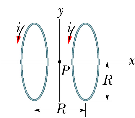
If the Helmholtz coils consists of n turns of wire, so the equivalent current in a one-turn coil is n times the current I in the n-turn coil.
Start with the formula for the on-axis field due to a single wire loop (which is itself derived from the Biot–Savart law)
 ,
,
The Helmholtz coils consists of n turns of wire, so the equivalent current in a one-turn coil is n times the current I in the n-turn coil. Substituting  for
for  in the above formula gives the field for an n-turn coil:

In a Helmholtz coil, a point P is halfway between the two loops has value equal to
 , so calculate the field strength at that point P by substituting
  in the above formula:

Since there are two coils instead of one, the field strength at the midpoint will be twice the single coil value

Examples
- A solenoid has length of 1.23 m and diameter 4 cm. if has five layers of windings of 850 turns each and carries a current of 5.57A. What is the magnitude of the magnetic field at the centre of the solenoid?
Solution:
Given:  ,
,  ,
,  ,
, 
- A 10 cm long solenoid has a total of 400 turns of wire and carries a current of 2A. Calculate the magnetic field inside near the centre.
Solution:
Given:  ,
,  ,
,  ,
, 
- A long solenoid consists of 20 turns per cm. What current is necessary to produce a magnetic field of 20mT inside the solenoid?
Solution:
Given:  ,
, 
- Calculate the magnetic field at a point along the axis of a long solenoid having 200 turns per metre, when a current of 2A flows through the solenoid. What will be the magnetic field if the point lies at one end of the solenoid?
Solution:
Given:  ,
, 
. At the centre of the solenoid
. At one end of the solenoid
- A 32 cm long solenoid of 1.2 cm in diameter is to produce 0.2T magnetic field at its centre. If current in solenoid is 3.7A. How many turns must the solenoid has?
Solution:
Given:  ,
,  ,
, 
- Two parallel co-axial circular coil of equal radius of 15 cm and 50 number of turns which carrying equal currents of 5A each in the same direction and separated by distance of 15 cm. Calculate the magnetic field on the axis around the mid-point between two coils.
Solution:
Given:  ,
,  ,
, 
Ampere’s Law
Ampere’s law provides an alternative formulation of the relation between a magnetic field and its sources. In some problems it is more convenient than the law of Biot-Savart.
Ampere’s law states that, the line integral of magnetic flux density B around a closed path is equal to  times the current I, passing through the closed circuit.
Mathematically, this law is written as  where is the permeability of a material,
  is the angle between a short length of a path
  and direction of the field at that point.
APPLICATION OF AMPERE’S LAW
Field of a long straight cylindrical conductor
Consider a long straight cylindrical conductor of radius R, carrying current I which is uniformly distributed over the cross section as shown in the figure below.

By applying Ampere’s law,  , to the circular loop of radius
  .
.
The fraction of current inside the loop is 


The magnetic field at radius :
:  This is the required expression
Examples:
- A long straight solid conductor of radius 5 cm carries a current of 2A which is distributed uniformly over its circular cross-section. Find the magnitude of magnetic field induction at the distance 3 cm from the axis of the conductor.
Solution:
Given:  ,
,  ,
, 
- A long straight solid conductor of radius 4 cm. What uniformly distributed current over its circular cross-section is required to produce a magnetic field of 7.5 x 10⁻⁶T at a distance of 3 cm from the axis of the centre O?
Solution:
Given:  ,
,  ,
, 
Magnetic Field of a Long Solenoid
Consider a long solenoid having  number of turns per unit length and carrying current
  as shown in the figure below;

The magnetic field inside the solenoid is uniform which is directed along the axis of solenoid. In a closed loop  above,
  . If
. If  be the small line element and the direction of
  is along
 . The angle between solenoid and
  is
is . If N be the number of turns in the closed loop
  Therefore

Magnetic Field of Toroid
The figure below represents a toroid wound with a wire carrying a current I.

Let  be the number of turns of wire per unit length of the toroid and
  be the current flowing through it.
From Ampere’s Law,
The line integral of the magnetic field along the circular path of radius  is
is 
But the total current passing through circle of radius  is
is  and
and  is
is  , Therefore
Examples:
- A toroid has a core (non-ferromagnetic) of inner radius 20 cm and outer radius 25 cm around which 1500 turns of a wire are wound. If the current in the wire is 2A. Calculate the magnetic field inside the toroid.
Solution:
Given:  ,,
,,  ,
,
- A toroidal coil has 3500 turns. Inner and outer diameters are 25 cm and 26 cm respectively. Calculate the magnetic field inside the coil when it carries a current of 11A.
Solution:
Given:  ,, ,
,, ,
- A toroid coil of inner radius 15 cm and outer radius 17 cm is wounded from 1200 turns of a wire. What are
- Maximum and
- Minimum magnetic field strengths within the toroid when the current of 10A flow.
Solution:
Given: , , , ,
, , ,
(Maximum)
(Minimum)
CHAPTER TWO


 and The force per unit length is given by;


 ,
,  ,
, 


 for
for 


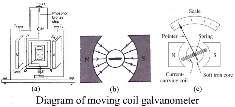
Moving coil galvanometer consists of a rectangular coil having large number of turns wound on a non-metallic frame. The coil is suspended between two poles of a permanent magnet which are cylindrical in shape. The coil is suspended by a phosphor – bronze strip which acts as path for the current to the coil. The strip is finally connected to the terminal T2 of the galvanometer. The other end of the coil is connected to a light spring which is finally connected to the terminal T1 as shown in figure below. The spring exerts a very small restoring couple on the coil. A piece of soft iron is placed within the frame of the coil. A plane circular mirror M is attached to the suspension to note the deflection of the coil using lamp and scale arrangement.


 ,
,


 where m is a mass of charged particle, v=velocity of a particle, B is magnetic field, r is the radius of circular path and q is a charged particle
 where
where  is the flux linkage in webers, t is time in second, E is induced emf in volt, N is the number of turns in a coil,
  is the rate of flux change in one turn and
  , and negative sign represent Lenz’s law which states that, the induced current will create a magnetic field which opposes the change in magnetic field that created the current as shown in the diagram below.


 ,
,

 ,
,


 where L is a constant known as coefficient of self induction.


 and the magnetic flux through each turn of the solenoid is given by;
  but
but 

 where L is coefficient of self induction which measured by Henry(H)


 ,
,  ,
, 

 but
but 


 . Where M is the constant depending upon both the coils and the permeability of the core C and called coefficient of mutual induction or mutual inductance of the two coils.


 measured by Henry (H)


 , where A is the cross sectional area of a coil 1 and
  is the length of a coil


 ,
,  ,
,  ,
,  ,
, 

 ,
,  ,
,  ,
, 

 ,
,  ,
, 

Answer: The emf is generated by the motion of the rod. According to Eq. (204), the magnitude of the motional emf is
CHAPTER TWO
- THE FORCE DUE TO CURRENT CARRYING CONDUCTORS
The magnetic field exerts a force on a moving charge or current in the field, the force on a conductor is always at right angles to the plane which contain both the conductor and the direction of the field in which it is placed. If the conductor makes angle  with the field, force on it is proportional to
  . So the maximum force is exerted when the conductor is perpendicular to the field, when =1.
For a moving charge, the magnetic force is directly proportional to the charged particle’s speed.
Thus, the force on a charge  moving with a velocity
  in a magnetic field
  is given by;
  where
where  is vector product, and therefore;
Example:
- A proton beam moves through a region of space where there is a uniform magnetic field of magnitude 2.0 T, the proton have velocity of magnitude
in the direction of
from magnetic field. Find the force on a proton (
).
Given: ,
,  ,
,  ,
, 
- An electron beam moving with a velocity of 106 ms-1, moves through a uniform magnetic field of 0.1 T which is perpendicular to the direction of the beam. Calculate the force on an electron if the electron charge if
Given: ,
,  ,
,  ,
,
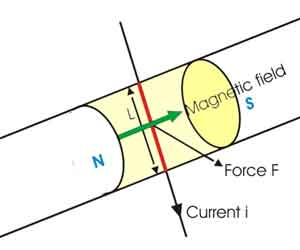
- Fleming’s Left-Hand Rule
Fleming’s Left – Hand Rule gives the direction of motion for the case when field and current are at right angles.
The figure below show that, a portion of a conductor of length L placed vertically in a uniform horizontal magnetic field strength B, produced by two magnetic poles N and S
- Magnetic Force on a Current Carrying Conductor
If the conductor has the length , the velocity of the moving charge
  in length
  at right angle to magnetic field direction is given
 .
.
From 

Example
- A wire carrying a current of 10A and 2 metres in length is placed in a field of flux density of 0.15 T. what is the force on the wire if it is placed;
- At right angles to the field
- At 450 to the field
- Given:
,
,
,
- Given:
,
- Suppose the coil has a radius of 3 cm, 10 turns and the radial field is 0.4 T. what is the force, if a current of 5mA flows in the coil?
Given: ,
,  ,
,  ,
,  ,
, 
- A wire of length 150 cm carrying an electric current of 0.1 A in the negative x direction and perpendicular to a magnetic field B, experiences a force of 6.0 × 10⁻³ N in the positive y direction due to a magnetic field. Find the magnitude of the magnetic field
Given: ,
,  ,
,  ,
,
- A wire carrying a 30.0 A current passes between the poles of a strong magnet that is perpendicular to its field and experiences a 2.16 N force on the 4.00 cm of wire in the field. What is the average field strength?
Given: ,
,  ,
,  ,
,
- What is the angle between a wire carrying an 8.0 A current and the 1.2 T field it is in if 50.0 cm of the wire experiences a magnetic force of 2.40 N? (b) What is the force on the wire if it is rotated to make an angle of 90º with the field?
Given: a).  ,
,  ,
,  ,
,
b).  , , ,
, , ,
- What force is exerted on the water in an MHD drive utilizing a 25.0-cm-diameter tube, if 100-A current is passed across the tube that is perpendicular to a 2.00-T magnetic field?
Given: ,
,  ,
, 
- Magnetic Force between two long and parallel current carrying conductor
The force between parallel current carrying conductors depends on the direction of current flow;
If current flow is in the same direction, then the wires will attract (see figure (a)). If it is opposite directions, then the wire will repel (see figure (b)) below.
If two long straight conductors X and Z lie parallel and close together at a distance r apart, and carry currents  and
and  respectively then the current of a conductor X is in a magnetic field of B equal to
  due to the current
  of a conductor Z. Thus the force on X is given by;
Example:
- A current of 10 A flows through each of two parallel long wires. The wires are 4 cm apart. Calculate the force exerted per unit length of the wire.
Given:  ,
, 
- A long straight conductor X carrying a current of 2 A is placed parallel to a short conductor Y of length 0.05 m carrying a current of 3 A. the two conductors are 0.1 m apart. Calculate the approximate force on Y.
Given:  ,
,  ,
, 

- A short conductor of length 5.0 cm is placed parallel to a long conductor of length 1.5 m near its centre. The conductors carry currents of 4.0 A and 3.0 A respectively in the same direction. What is the total force experienced by the long conductor, when they are 30 cm apart?
Given:  ,
,  ,
, 
- A current of 20 A flows through each of the two parallel long copper conductors 4 cm apart. Calculate the force exerted per unit length of each conductor
Given:  ,
,
- A 2.50-m segment of wire supplying current to the motor of a submerged submarine carries 1000 A and feels a 4.00-N repulsive force from a parallel wire 5.00 cm away. What is the magnitude of the current in the other wire?
Given:  ,
,  ,
,  ,
, 
- The wire carrying 400 A to the motor of a commuter train feels an attractive force of 4.0 x 10⁻³ N/m due to a parallel wire carrying 5.0 A to a headlight. (a) How far apart are the wires? (b) Are the currents in the same direction?
Given:  , ,
, ,  ,
, 
- Definition of Ampere
In defining Ampere in terms of force between conductors the two infinitely long parallel straight conductors are considered to carry a current of one ampere and separated by one metre apart.
Therefore, the ampere can be defined in terms of force between conductors as follows
The Ampere is that current which when flowing in two infinite parallel wires one metre apart produces a force between them of 2 x 10⁻⁷ N/m
Proof:
- Working of a Moving Coil Galvanometer and its sensitivity
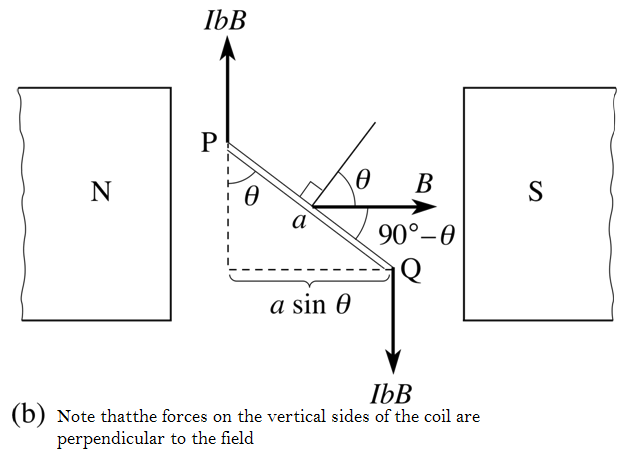
- Torque on Rectangular Coil in Uniform Field
A rectangular coil of insulated copper wire is used in the moving coil meter which used to measure current and potential difference.
Consider the forces produced by a magnetic field on the rectangular coil PQRS, of dimensions a and b, shown in figure (a) below. The coil carries a current I, and its instantaneous orientation may be described by the angle θ between the magnetic field B and a ‘normal’ drawn perpendicular to the plane of the coil. The sections SP and QR of the loop (current at 90° to the field) will each experience a magnetic force of magnitude IbB, directed as shown in the figure (a). The sections PQ and RS of the loop (current at (90° − θ) to the field) will each experience a magnetic force of magnitude IaB cos θ, directed vertically, as shown in the figure (a).
Figure (b) shows this in plan view. It is apparent that the forces on PQ and RS are also opposites and have the same line of action. The forces on SP and QR are also opposites but their lines of action are displaced; together they constitute a couple and exert a torque on the coil about a vertical axis XY through the centre of the coil. This torque will tend to rotate the coil, unless its plane is already perpendicular to the magnetic field (θ = 0), in which case the forces on SP and QR have the same line of action and give no torque.
When the normal to the coil makes an angle θ with the field, the magnitude of the total magnetic torque about the axis XY, caused by the two forces IbB, each at a perpendicular distance of (a sin θ)/2 from the axis, is given by:
This can also be written as:  where A = ab, the area of the coil.
If the coil has N identical turns, each of area A, each loop experiences this same torque and the total torque is increased by a factor N then;  where NA is the effective area of the coil.
Torque  is the Force x Arm of the couple
Example:
- A rectangular coil of 10 cm by 5 cm of 20 turns is hinged at one side and a current of 0.1 A pass through it. What torque acts on it, if it is mounted with its plane at an angle of 300 to the direction of uniform magnetic field of 0.5 T?
Given;  ,
,  ,
,  ,
,  ,
, 
- A vertical rectangular coil of sides 5 cm by 2 cm has 10 turns and carries a current of 2 A. Calculate the torque on a coil when it is placed in a uniform horizontal magnetic field of 0.1 T with its plane
- parallel to the field (2 x 10⁻³Nm)
- perpendicular to the field
- 600 to the field
Given;  ,
,  ,
,  ,
,  ,
, 
- Parallel to the field
- Perpendicular to the field
to the field is the same
to the normal
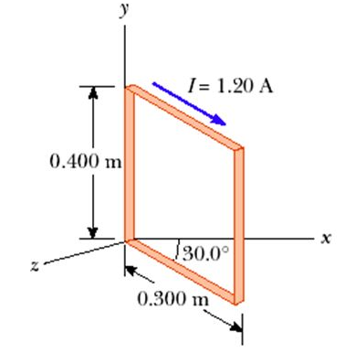
- A rectangular coil consists of N=100 closely wrapped turn and has dimensions a=0.4 m and b=0.3 m. The coil is hinged along the y-axis and its plane makes an angle θ = 300 with the x-axis. What is the magnitude of the torque exerted on the coil by uniform magnetic field B = 0.8 T directed along the x – axis when the current is I=1.2 A in the direction shown?
Given;  ,
,  ,
,  ,
,  , to the normal of the field
- A rectangular coil with 200 turns is 5.0 cm high by 4.0 cm wide when the coil is placed in a magnetic field of 0.35 T. its maximum torque is 0.22 Nm. What is the current in the coil.
Given;  ,
,  ,
,  ,
,  ,
, 
- A circular coil of a wire 0.05 m in radius, having 30 turns lies in a horizontal plane. It carries a current of 5 A, in a counter – clockwise sense when viewed from above. The coil is in a magnetic field directed toward the right, with magnitude 1.2 T. Find the torque on the coil?
Given;  ,
,  ,
,  ,
, 
 ,
, 
- A circular coil of wire 8 cm in diameter has 12 turns and carries a current of 5 A. the coil is in a region where the magnetic field is 0.6 T
- What is the maximum torque in the coil? (0.18 Nm)
- In what position would the torque be one-half as greater as in (a)? ( 300 )
Given;  ,
,  ,
,  ,
, 
 ,
,
- Moving Coil Galvanometer
A moving coil galvanometer is a device which is used to detect and measure small electric current. It is the basic components of most of the measuring instrument including ammeters and voltmeters. It is the most sensitive instrument.
Moving coil galvanometer works on the principle that a current carrying coil placed in a magnetic field experiences a torque. Its operation is based on the principle that when a current carrying loop or coil is placed in a uniform magnetic field, the coil experiences a torque.
Moving coil galvanometer consists of a rectangular coil having large number of turns wound on a non-metallic frame. The coil is suspended between two poles of a permanent magnet which are cylindrical in shape. The coil is suspended by a phosphor – bronze strip which acts as path for the current to the coil. The strip is finally connected to the terminal T2 of the galvanometer. The other end of the coil is connected to a light spring which is finally connected to the terminal T1 as shown in figure below. The spring exerts a very small restoring couple on the coil. A piece of soft iron is placed within the frame of the coil. A plane circular mirror M is attached to the suspension to note the deflection of the coil using lamp and scale arrangement.
Let PQRS be a single turn of the coil (in the figure above). A current I flows through the coil. In a radial magnetic field, the plane of the coil is always parallel to the magnetic field. Hence the sides QR and SP are always parallel to the field. So, they do not experience any force. The sides PQ and RS are always perpendicular to the field.
PQ = RS = l, length of the coil and PS = QR = b, breadth of the coil.
Force on PQ, F = BI (PQ) = BIl. According to Fleming’s left hand rule, this force is normal to the plane of the coil and acts outwards.
Force on RS, F = BI (RS) = BIl.
This force is normal to the plane of the coil and acts inwards. These two equal, oppositely directed parallel forces having different lines of action constitute a couple and deflect the coil. If there are n turns in the coil,
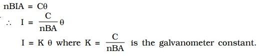
Moment of the deflecting couple = n BIl x b = nBIA
When the coil deflects, the suspension wire is twisted. On account of elasticity, a restoring couple is set up in the wire. This couple is proportional to the twist. If θ is the angular twist, then,
Moment of the restoring couple = Cθ, where C is the restoring couple per unit twist
At equilibrium, deflecting couple = restoring couple nBIA = Cθ
Since the deflection is directly proportional to the current flowing through the coil, the scale is linear and is calibrated to give directly the value of the current.
Example:
- The rectangular coil of a galvanometer has 50 turns. The side perpendicular to the rotating axis is 3.0 cm long and the side parallel to the rotating axis is 2.0 cm long. The coil is placed in a radial magnetic field of 0.010 T. The torsion coefficient of the hair spring on which the coil hangs is 1.0 x 10⁻⁸ Nmrad-1 Determine the deviation of the galvanometer’s hand if the current through the coil is 1.0 mA
Given:  ,
,  ,
,  ,
,  ,
, 
- The coil of a galvanometer is 0.02 x 0.08 m2 and contains 200 turns of fine area. If restoring couple constant of suspension fibre is 10-6Nm/degree and coil is suspended by fibre in a magnetic field of 0.2T.
- What is the maximum current that can be measured by this galvanometer if the scale can accommodate a deflection of 450?
- What is the smallest current that can be measured if the minimum observable deflection is 0.10
Given:  ,
,  ,
,  ,
,  ,
, 
- A circular coil of 30 turns and radius 8.0 cm carrying a current of 6 A is suspended vertically in uniform horizontal magnetic field of magnitude 1.0 T. The field line makes an angle of 600 with the normal to the coil. Find the magnitude of counter torque that must be applied to prevent from turning.
Given:  ,
,  ,
,  ,
, 
 ,
, 
- A galvanometer coil 2 cm x 2 cm wound with 100 turns is suspended vertically in a field of 0.045 T and the suspension requires a torque of 0.09 x 10⁻⁷Nm to twist it through 1 radian. What steady current maintained in the coil will produce a deflection of 100? [ 10=0.0174 rad]
Given:  ,
,  ,
,  ,
,  ,
, 
- A galvanometer coil 4 cm x 2 cm wound with 1000 turns is suspended vertically in a field of 0.05 T. The wire used for suspension needs a torque of 1.25 x 10⁻⁸Nm to twist it through 1 radian. What steady current flowing in the coil if deflection is 500? [10=0.0174 rad]
Given:  ,
,  ,
,  ,
,  ,
, 
- Sensitivity of Moving Coil Galvanometer
- Current Sensitivity of a Galvanometer
The current sensitivity of a galvanometer is defined as the deflection produced when unit current passes through the galvanometer. A galvanometer is said to be sensitive if it produces large deflection for a small current.
The current sensitivity of a galvanometer can be increased by
- Increasing the number of turns
- Increasing the magnetic induction
- Increasing the area of the coil
- Decreasing the couple per unit twist of the suspension wire. This explains why phosphor-bronze wire is used as the suspension wire which has small couple per unit twist.
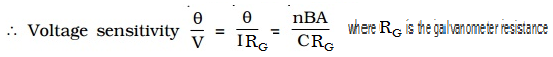
- Voltage sensitivity of a galvanometer
The voltage sensitivity of a galvanometer is defined as the deflection per unit voltage.
An interesting point to note is that, increasing the current sensitivity does not necessarily, increase the voltage sensitivity. When the number of turns (n) is doubled, current sensitivity is also doubled. But increasing the number of turns correspondingly increases the resistance RG. Hence voltage sensitivity remains unchanged.
The voltage sensitivity can be increased by;
- Increasing number of turns of the coil (N)
- Increasing magnetic field intensity (B)
- Increasing area of the coil (A)
- Decreasing restoring torque per unit twist of the suspension (K)
- Decreasing resistance (R)
The advantage of moving coil galvanometer
- The sensitivity of the galvanometer can be increased by increasing N, B and A while decreasing the value of k
- The instrument has a linear scale
- Since the instrument uses high value of B, the deflection is undisturbed by earth’s magnetic field
- As the coil is wound on the nonmagnetic metallic frame, damping is produced by eddy currents, as a result the coil quickly assumes the final position
- Conversion of galvanometer into an ammeter
A galvanometer is a device used to detect the flow of current in an electrical circuit. Even though the deflection is directly proportional to the current, the galvanometer scale is not marked in ampere. Being a very sensitive instrument, a large current cannot be passed through the galvanometer, as it may damage the coil. However, a galvanometer is converted into an ammeter by connecting a low resistance in parallel with it. As a result, when large current flows in a circuit, only a small fraction of the current passes through the galvanometer and the remaining larger portion of the current passes through the low resistance. The low resistance connected in parallel with the galvanometer is called shunt resistance. The scale is marked in ampere.
The value of shunt resistance depends on the fraction of the total current required to be passed through the galvanometer. Let Ig be the maximum current that can be passed through the galvanometer. The current Ig will give full scale deflection in the galvanometer.
Galvanometer resistance = Rg
Shunt resistance = Rs
Current in the circuit = I
∴ Current through the shunt resistance Is = (I-Ig)
Since the galvanometer and shunt resistance are parallel, potential is common.
The shunt resistance is very small because Ig is only a fraction of I.
The effective resistance of the ammeter Ra is (Rg in parallel with RS)
Ra is very low and this explains why an ammeter should be connected in series. When connected in series, the ammeter does not appreciably change the resistance and current in the circuit. Hence an ideal ammeter is one which has zero resistance.
- Conversion of galvanometer into a voltmeter
Voltmeter is an instrument used to measure potential difference between the two ends of a current carrying conductor. A galvanometer can be converted into a voltmeter by connecting a high resistance in series with it. The scale is calibrated in volt. The value of the resistance connected in series decides the range of the voltmeter.
Galvanometer resistance = Rg
The current required to produce full scale deflection in the galvanometer = Ig
Range of voltmeter = V
Resistance to be connected in series = Rs
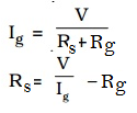
Since RS is connected in series with the galvanometer, the current through the galvanometer,
From the equation the resistance to be connected in series with the galvanometer is calculated
The effective resistance of the voltmeter is
Rv = RG + Rs
Rv is very large, and hence a voltmeter is connected in parallel in a circuit as it draws the least current from the circuit. In other words, the resistance of the voltmeter should be very large compared to the resistance across which the voltmeter is connected to measure the potential difference. Otherwise, the voltmeter will draw a large current from the circuit and hence the current through the remaining part of the circuit decreases. In such a case the potential difference measured by the voltmeter is very much less than the actual potential difference. The error is eliminated only when the voltmeter has a high resistance. An ideal voltmeter is one which has infinite resistance.
Examples:
- A galvanometer of resistance 20Ω gives full scale deflection with a current of 2mA. What size resistance should be connected in parallel so that it may measure 2A on full scale deflection?
Given;  ,
,  ,
, 
- A galvanometer of resistance 100Ω gives full scale deflection for 10mA current. What should be the value of shunt so that it can measure a current of 100mA?
Given;  ,
,  ,
, 
- A DC milliammeter has a resistance of 12Ω and gives full scale deflection for a current of 0.01A. to convert it into voltmeter giving a full scale deflection for 3V. What the resistance required to be put in series with the instrument?
Given:  , ,
, , 
- A galvanometer of resistance 100Ω gives full scale deflection for a current of 10-5A. What size of shunt required to convert it into an ammeter of 1A range?
Given:  ,
,  ,
, 
,
- The resistance of a moving coil galvanometer is 20Ω. It requires 0.01A current for full scale deflection. What the value of resistance required to convert it into a voltmeter of range 20 volt?
Given: , , 
,
- A galvanometer with a coil of resistance 12 Ω shows full scale deflection for a current of 2.5mA. how will you convert the meter into;
- An ammeter of range 0 to 7.5A
- A voltmeter of range 0 to 10V
Given:  , ,
, ,  ,
,
- To convert galvanometer into ammeter, a resistance Rs is connected in parallel with galvanometer coil whose value is given by;
- To convert galvanometer into voltmeter, a resistance Rs is connected in series with the galvanometer whose value is given by;
- Motion of a charged particle in a magnetic field
A charged particle experiences a force when moving through a magnetic field which depending with the path followed by a particle.
- Motion of a charged particle in a magnetic field parallel to the field
When a charged particle moves parallel to the magnetic field i.e.,  , there is no force acting on it. It velocity remains unchanged and its path is a straight line as shown in the figure below.
- Motion of a charged particle in a magnetic field perpendicular to the field
Consider a particle moving in an external magnetic field with velocity perpendicular to the field. The force is always directed toward the centre of the circular path. The magnetic force causes a centripetal acceleration that changing the direction of the velocity of the particle as shown in the figure below.
No work is done by the magnetic field and kinetic energy of the charged particle remains constant.
In the magnetic field the force is always at right angles to the motion of the charge and the resulting path of the charge is circular.
Therefore;
Examples
- The path of electron in a uniform magnetic field of flux density 0.01T in vacuum is a circle of radius 0.05m. Given that the charge and mass of electron are -1.6 x 10⁻¹⁹C and 9.1 x 10⁻³¹kg respectively. Find the;
- Speed
- Period of its orbit.
Given:  , , ,
, , ,
- An electron is accelerated from rest through a potential difference of 5000V and then enters a magnetic field of strength 0.02T acting at right angle to its path with the speed of 4.2 x 10⁷ms-1. Calculate the radius of the resulting electron orbit.
Given: ,  , , ,
, , , 
- A proton is moving in a circular orbit of radius 14cm in a uniform 0.35T magnetic field directed perpendicular to the velocity of the proton. Find the
- Velocity of the proton
- Period of the circular motion of the proton
(Use , )
Given: ,  ,
,  ,
,
- ,
,
- A 10 eV electron is circulating in a plane at right angles to uniform magnetic field of induction 1.0 x 10⁻⁴T
- Find the radius of its orbit
- Find the time period of revolution
- Find the angular frequency
Use 1eV=1.6 x 10⁻¹⁹J, mass of electron=9.1 x 10⁻³¹kg
Given:  , ,
, ,  ,
, 
- but
- A charged particle moving at constant speed enters a uniform magnetic field and moves at right to the field. Explain why the particle moves in a circle.
Solution:
When the charged particle enters the magnetic field there is a force on it. The force is at right angles to its direction of motion. Therefore its speed does not change, only its direction of motion changes, as it turns the force always remains at right angle to the direction of motion. Thus the particle moves in a circular path.
NB: if a particle’s velocity makes angle with the magnetic field, the component of the velocity along magnetic field will not change; a particle with a initial velocity at an angle to the field will move in a helical path.THE ELECTRIC CURRENT INDUCED BY A CHANGING MAGNETIC FIELD
Faraday discovered that a voltage would be generated across a length of wire if that wire was exposed to a perpendicular magnetic flux of changing intensity. The flux will be at its maximum as the magnet is aligned perpendicular to the wire. The magnitude of the changing flux and the voltage are linked. If the lines of flux are parallel to the wire, there will be no induced voltage.
FARADAY’S, LENZ LAWS AND FLAMING RIGHT RULE
The first law of Faraday’s electromagnetic induction states that, whenever a conductor are placed in a varying magnetic field emf are induced which is called induced emf, if the conductor circuit are closed, current are also induced which is called induced current.
The second law of Faraday’s electromagnetic induction states that, the induced emf is equal to the rate of change of flux linkages (flux linkages is the product of turns, n of the coil and the flux associated with it). Mathematically this expression is represented as
The induced emf in a coil can increased by;
- Increasing the number of turns in the coil
- Increasing magnetic field strength
- Increasing the speed of the ralative motion between the coil and the magnet
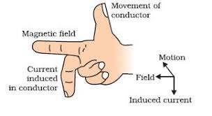
Fleming Right Hand Rule
According to Fleming’s right hand rule the thumb, fore finger and middle finger of right hand are stretched perpendicular to each other as shown in the figure and id thumb represents the direction of movement of conductor, forefinger represents direction of the magnetic field, then the middle finger represents direction of the induced current as shown below.
Examples;
- A plane circular loop of conducting wire of radius
cm which possesses
turns is placed in a uniform magnetic field. The direction of the magnetic field makes an angle of
with respect to the normal direction to the loop. The magnetic field-strength
is increased at a constant rate from
to
in a time interval of
s.
- What is the emf generated around the loop?
- If the electrical resistance of the loop is
, what current flows around the loop as the magnetic field is increased?
Given:  ,
,  ,
,  ,
,  ,
,  ,
,  ,
, 
Thus, the emf generated around the loop is 0.163V
- A flat square coil of 5 turns with 0.5 m on each side and ha s magnetic field of 0.5 T passing through it. The plane of the coil is perpendicular to the magnetic field. Use Faraday’s law to calculate the induced e.m.f, if the magnetic field is increases uniformly from 0.5T to 1.0T in 10 sec.
Given;  ,
,  ,
,  ,
,  ,
, 
- Consider a flat square coil with N = 5 loops. The coil is 20 cm on each side, and has a magnetic field of 0.3 T passing through it. The plane of the coil is perpendicular to the magnetic field: the field points out of the page.
- If nothing is changed, what is the induced emf?
There is only an induced emf when the magnetic flux changes, and while the change is taking place. If nothing changes, the induced emf is zero.
- The magnetic field is increased uniformly from 0.3 T to 0.8 T in 1.0 seconds. While the change is taking place, what is the induced emf in the coil?
Given;  ,
,  ,
,  , ,
, , 
- While the magnetic field is changing, the emf induced in the coil causes a current to flow. Does the current flow clockwise or counter-clockwise around the coil?
By apply Lenz's law, as well as the right-hand rule. While the magnetic field is being changed, the magnetic flux is being increased out of the page. According to Lenz's law, the emf induced in the loop by this changing flux produces a current that sets up a field opposing the change. The field set up by the current in the coil, then, points into the page, opposite to the direction of the increase in flux. To produce a field into the page, the current must flow clockwise around the loop. This can be found from the right hand rule.
One way to apply the rule is this. Point the thumb on your right hand in the direction of the required field, into the page in this case. If you curl your fingers, they curl in the direction the current flows around the loop - clockwise.
- A certain coil of a wire consists of 500 circular loops of radius 4 cm. it is placed between the poles of a large electromagnet, where the magnetic field is uniform, perpendicular to the coil and increasing at rate of 0.2Ts-1. What is the magnitude of the resulting induced emf?
Given; ,
,  ,
, 
MOTIONAL EMF
If a rod of length L moves with velocity v in a direction perpendicular to a uniform and time independent magnetic field B, an emf is induced in the rod. If in figure below the rod XY is free to move on a conductor ABCD towards the right with a constant velocity v. Assume that the rod XY and the conductor ABCD is frictionless so that there is no loss of energy. The area enclosed by XBCY changes as the rod XY moves. The uniform magnetic field B is perpendicular to the plane of the area XBCY.
Let the length XB be x. As the area enclosed by XBCY changes, the magnetic flux enclosed by the loop changes. As the magnetic flux is changing, an emf will be induced. This induced emf is given by
If the conductor does not move at right angles (90°) to the magnetic field then the angle θ° will be added to the above expression giving a reduced output as the angle increases
Example:
- Consider the circuit below. Suppose that the length of the moving rod is
m, its speed is
, the magnetic field-strength is
T (the field is directed out of the page and the resistance of the circuit is
.
- What is the emf generated around the circuit?
- What current flows around the circuit?
- What is the magnitude of the force acting on the moving rod due to the fact that a current is flowing along it?
- What is the rate at which work must be performed on the rod in order to keep it moving at constant velocity against this force?
- What is the rate at which electrical energy is generated?
- What is the rate at which energy is converted into heat due to the resistivity of the circuit?
Solution:
Given;  ,
,  ,
,  ,
,  ,
,
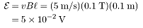
- The magnitude of the motional emf is:
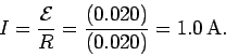
- The anti-clockwise current driven around the circuit by the motional emf follows from Ohm's law:
- The total force acting on the rod is of magnitude:
- The rate
at which work is done by this force is the product of the force and the velocity of the rod in the direction of this force:
- The rate at which electric charges acquire energy in the circuit is:
- The rate at which electrical energy is converted into heat energy in the circuit is:
- The magnetic field in a region between the pole faces of an electromagnetic is 0.5 T. find the induced emf in a straight conductor of 1 m long perpendicular to magnetic field B and moving perpendicular to both to B and its length with a velocity of 1 ms-1
Given;  ,
,  ,
,  ,
,
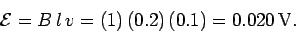
- A bar of length 10 cm slides along metal rails at a speed of 5 m/s in a magnetic field of 0.1 T. What is the motional emf induced in the bar and rails?
Given;  ,
,  ,
,
EMF OF ROTATING WHEEL/DISC
Consider a disc of radius  from centre along the rod OA, as shown in the figure below.
As the disc rotates, the linear velocity of a spoke end at the rim  and linear velocity of spoke end at the axle
Average linear velocity, 
Therefore the emf induced 
Examples:
- An aluminium disc of diameter 20 cm is rotating at 20 rev/s about an axis. If the plane of a disc is perpendicular to a uniform magnetic field of flux density 0.5 T, find the potential difference between the centre and circumference of the disc.
Given;  ,
,  , ,
, ,
- A metallic rod of 1 m length is rotated with a frequency of 50 rev/s, with one end hinged at the centre and the other end at the circumference of a circular metallic of the ring of radius 1m, about an axis passing through the centre and perpendicular to the ring. A constant and uniform magnetic field of 1 T parallel to the axis is present everywhere. What is the emf between the centre and the metallic ring?
Given;  ,
,  ,
,  ,
,
SELF INDUCTION AND MUTUAL INDUCTION
SELF INDUCTION
Self induction is the induction of a voltage in a current carrying wire when the current in the wire itself is changing. In the case of self inductance, the magnetic field created by a changing current in the circuit itself induces a voltage in the same circuit therefore, the voltage is self induced.
If  is the amount of current flowing in the coil at any instant then emf induced in the coil is directly proportional to the change in current.
From the Faraday’s and Lenz’s Laws induced emf is;
If the coil has N number of turns then total flux through the coil is  where
where  is flux through single turn of the coil.
SEIF INDUCTION OF A LONG SOLENOID
Consider a long solenoid of length L, area of cross – section A and having N closely wound turns.
If is the amount of current flowing through the solenoid then, magnetic field  inside the solenoid is given by,
If the solenoid carries a core of relative permeability , then
Examples:
- When a current of 2.5A is passed through a coil of 500 turns, the magnetic flux produced 1.4 x 10⁻⁴ Wb. What is the induction of the coil?
Given;  ,
,  ,
,  ,
,
- If current in a 130mH coil changes steadily from 20mA to 28mA in 140ms. Find the magnitude of induced emf.
Given;  ,
,  ,
,  ,
,  ,
,
- An air-cored solenoid having a diameter of 4cm and a length of 60cm is wound with 4000 turns.
a) Find the inductance of the solenoid,
b) If it has an iron core of relative permeability is 4000, what will be the inductance of a solenoid
Given;  ,
,  ,
,  ,
,  ,
,
- Find the change in current in an inductor of 10H in which the emf. Induced is 300V in 10-2s. also find the change in magnetic flux.
Given;  ,
,  ,
,  ,
,
- The inductance of a coil having 200 turns is 10mH. Calculate the total flux linked with coil corresponding to a current of 4mA. (4x10⁻⁵Wb)
ENERGY STORED IN AN INDUCTOR
Changing current in an inductor gives rise to self induced emf which opposes changes in the current flowing through the inductor. Therefore a certain amount of work is required to be done against this self induced emf for establishing the current in the circuit. The source supplying current in a circuit must maintain p.d between its terminals which is done by supplying energy to the inductor.
Power supplied to the inductor is given by:
Example:
- A current of 20mA is passing through a coil of inductance 500mH. Find the magnetic energy stored in the coil.
Given;  ,
,  ,
,
- A battery of emf 12 V is suddenly connected in series with 30Ω resistor and 220mH inductor, when current in the circuit reaches half its maximum possible value, at what rate is;
- Energy being delivered by the battery
- Energy being stored in the magnetic field of the inductor?
Given;  ,
,  ,
, 
- Power being supplied by battery is
but
- Calculate the inductance and energy stored in the magnetic field of an air – cored solenoid 50cm long, 5cm in diameter and wound with 1000 turns, if carrying a current of 5A.
Given;  ,
,  ,
,  ,
, 
- A 100mH coil carries a current of 1A. What is the energy stored in the magnetic field?
Given:  ,
, 
- Calculate the self – inductance of a coil of 100 turns if a current of 2A gives rise to magnetic flux of 5 x 10⁻⁵Wb through the coil. Also calculate the magnetic energy stored in the medium surrounding the coil for the above of the current.
Given:  ,
,  ,
, 
- A electromagnet has stored 648 J of magnetic energy when a current of 9A exits in its coils. What average e.m.f is induced if the current is reduced to zero in 0.45second?
Given:  ,
,  ,
, 
MUTUAL INDUCTION
Mutual induction is the phenomenon in which a changing current in one coil induces an emf in another coil. The pair of coils or circuits are said to have mutual inductance, such circuits are called coupled circuits. The magnetic flux  linked with secondary coil depends upon the current
  in primary coil.
Consider two fixed coil with a varying current  in coil 1 of a length
  producing a magnetic field
  . The induced emf in coil 2 due to
  is proportional to the magnetic flux through coil 2.
If  is the number of loops in coil 2 and
  is the flux through a single loop in coil 2, then from,
but 
Therefore;
Example:
- Two identical coil A and B of 1000 turns each lie in parallel planes such that 80% of flux produced by one coil links with the other. A current of 5A flowing in coil A produces a flux of a 5mWb in it. If current in coil A changes from +12A to -12A in 0.02 second, calculate
- Mutual inductance between A and B
- E.m.f induced in coil B
Given:  ,
,  ,
,  ,
, ,
, 
- If the current in the primary coil is reduced from 3A to zero in 0.001 second, the induced e.m.f in the secondary coil is 1500V. Calculate the mutual inductance between the two coils.
Given:  ,
, 
- A toroid solenoid with an air core has an average radius of 15 cm, area of cross-section 12 cm2 and 1200 turns, a second coil of 300 turns is wound closely on the toroid above. If current in the primary coil is changed from zero to 2A in 0.05s. Find the induced e.m.f in the second coil.
Given:  ,
,  ,
,  ,
,  ,
, 
- A solenoid of length 50 cm with 20 turns per cm and area of cross-section 40cm2 complete surrounds another coaxial solenoid of the same length, area of cross-section 25cm2 with 25 turns per cm. calculate the mutual inductance of the system.
- A solenoid 70 cm in length and of 2100 turns has a radius of 4.5 cm. a second coil of 750 turns is wound upon the middle part of the solenoid. Find the mutual inductance between the two coils.
- What is the mutual inductance of a pair of coil if a current of 3A in one coil causes the flux in the second coil of 1000 turns to change by 10-4 Wb in each turn?
WORKING OF DC ELECTRIC MOTORS
.1 aaa
2. fff
3. Electric Current Induced by a Changing Magnetic Field
To analyses the principles related to induced emf and current by considering the following:
- Flux linkage, factors for the induced emf, Fleming’s Right-hand rule, Faraday and Lenz’s laws
- Mutual Induction and Self-Induction
- Energy stored in self and mutual induction
- The working of electric motor, a.c and d.c electrical generators
- The working principle of transformers
4. Magnetic Field of Earth
To analyze the origin, structure and components of the earth’s magnetic field,
To discuss the variations of the earth’s magnetic field
- What is the force per meter on a lightning bolt at the equator that carries 20,000 A perpendicular to the Earth’s 3.00 × 10⁻⁵-T field? (b) What is the direction of the force if the current is straight up and the Earth’s field direction is due north, parallel to the ground?
- 5. (a) A DC power line for a light-rail system carries 1000 A at an angle of 30º to the Earth’s 5.00 × 10⁻⁵-T field. What is the force on a 100-m section of this line? (b) Discuss practical concerns this presents, if any.
- 8. (a) A 0.750-m-long section of cable carrying current to a car starter motor makes an angle of 60º with the Earth’s 5.50 × 10⁻⁵ T field. What is the current when the wire experiences a force of 7.00 × 10⁻³ N? (b) If you run the wire between the poles of a strong horseshoe magnet, subjecting 5.00 cm of it to a 1.75-T field, what force is exerted on this segment of wire?
Answer: The emf is generated by the motion of the rod. According to Eq. (204), the magnitude of the motional emf is
The emf acts in the anti-clockwise direction in Fig. 36.
The anti-clockwise current driven around the circuit by the motional emf follows from Ohm's law:
Since the rod carries a current  which flows perpendicular to a magnetic field , the force per unit length acting on the rod is
  (see Sect. 8.2). Thus, the total force acting on the rod is of magnitude
This force is directed parallel to the vector  . It follows that the force is to the left in Fig. 36. In other words, the force opposes the motion producing the emf.
In order to keep the rod moving at a constant velocity, some external agent must apply a force to the rod which is equal and opposite to the magnetic force described above. Thus, the externally applied force acts to the right. The rate at which work is done by this force is the product of the force and the velocity of the rod in the direction of this force. Thus,
Every charge  which circulates around the circuit in the anti-clockwise direction acquires the energy
  . The amount of charge per unit time which circulates around the circuit is, by definition, equal to the current flowing around the circuit. Thus, the rate at which electric charges acquire energy in the circuit is
Now, the rate at which electric charges acquire energy in the circuit is equal to the rate at which mechanical work is done on the rod by the external force, as must be the case if energy is to be conserved. Thus, we can think of this circuit as constituting a primitive generator which transforms mechanical into electrical energy.
The rate at which electrical energy is converted into heat energy in the circuit is
Thus, all of the mechanical work done on the rod eventually ends up as heat dissipated in the circuit